By Brian Richards 18 September 2008
This article is provided for your personal use - Copyright remains with Brian Richards.
| NOT to be reproduced or copied without the express permission of the Author |
| This article was presented in a series of parts in the TR Register Australia journal - "Sidescreen" Explanatory photographs are at the foot of this article. |
EFI and the TR - Brian RichardsI am at a stage now where I am looking for a new project and the one that I have settled on is to EFI my TR3A. Sacrilege I hear you all saying. Well maybe, but then my TR is not really "original" as it is. Like most old timers, I really did not know much about EFI except for the last 20 years or so, all my cars have been fitted with EFI and I have only experienced one failure, an EGO sensor. I have never changed their points, set the distributor or oiled the dash pots. The cars always start, regardless of temperature, and never miss a beat. I may have been lucky but they are reliable and hence I have not had the need to learn how they work. In fact all those wires and tubes tend to turn you off. By searching the internet I have now learned a lot. I still do not understand the magic of computers but I do have some understanding of how the EFI system works. There is a great site that has a wealth of information. It is a DIY fuel injection site, www.megasquirt.info . It has a wealth of information on how it all works. What I have learned is that there are a number of aftermarket ECUs (Electronic Control Unit) ranging in price from a DIY kit for about $180.00 to a some upmarket ones costing many thousands of dollars. There are a number of local (Australian) manufacturers among them. One interesting point I found, is that the great majority of aftermarket ECUs sold go on to cars that are fitted with EFI from new. If you wish to modify the performance of a standard EFI engine then you can not simply change the carbie settings and fiddle with the distributor. Some say that is a good thing. You need to alter the programme of the ECU and you can not do that. Hence the sale of after market ECUs into the performance market. All the standard sensors and fittings are retained. Basically only the ECU is changed then programmed with a lap top to achieve the results required. It is much easier in fact than on a non EFI engine. With the TR we are going from Carbies to EFI, a much more complicated task as we have to modify the hardware. While sifting through all the advertising bumf and talking to two local performance shops, I was tending towards an Australian ECU for about $1000.00. It looked good and had all the features I wanted and more. On taking a step back, I realised I was getting away from my original intent, i.e. a "project". So I settled on a MegaSquirt 2 V3.0 kit from the USA for US$245.00. This kit (MS2) is really starting from scratch as you get a PCB (printed circuit board), a packet of resistors, transistor, etc, and a case to put it all into. My soldering technique will get a try out. The finished ECU will give me full fuel and ignition control as well as control of the engine cooling fan. The physical changes required are;
Before these changes are carried out, a critical decision needs to be made. What kind of injection system am I going to use. By that I mean, how many injectors, how many throttle bodies (TB) and how will the injectors be fired. This will affect the air handling system (manifolds etc) and throttle bodies. The throttle body is basically the butterfly, just like a carburettor. It is your connection to the engine. You can have one TB as is the case with most cars, two as is the case with the TR Carbies or, one per intake port as on EFI equipped motor bikes and outboard engines or the old Lucas system fitted to the TR6. There are then two ways to set up the injectors, one per intake port like most cars today (multi port) or fit them to the throttle body(s) and have one or two injectors for the whole engine like the early EFI Falcons and a lot of high performance V8s and drag cars. Still another choice is the method of firing the injectors, batch, bank or sequential. With batch injection, all the injectors fire at once but not timed to any particular cylinder. With bank injection, half the injector's fire at once but again not timed to any particular cylinder. Sequential injection is where each injector fires at a specific point in its cylinders cycle. With throttle body injection, they are usually batch or bank fired as they feed more than one, normally all, cylinders. Port injection is normally bank or sequential fired. Sequential injection is much more complex for the TR as you need a cam position sensor. Also the complexities would far outweigh the advantages. I imagined that with sequential injection the fuel would be directed straight into the open intake port but in fact at higher RPM and load, there is not time. The intake valve is only open for about 30% of the cycle and above about 2500RPM and 30% max HP the fuel required can not be injected fast enough. This means that fuel is injected onto closed valves, just like bank injection. OEMs use sequential injection to lower emissions at lower RPM. If you're good enough you can tune each cylinder individually and some high end cars do just that. So, which one for the TR? As the TR head has four intake ports, port injection is the natural choice. On an MGB you would have trouble as they have siamese ports. Next is the throttle body. The standard TR has two (SUs) and we could simply gut the carbies and use them on a standard manifold. The throttle set up and air cleaners can be retained. Also this would retain the "period" look of twin SUs. Another option is to fabricate a plenum chamber to connect the two flanges of a standard manifold and use one throttle body as do most cars today. You can find suitable ones at the wreckers. I got a 1987 Holden Camira one with all fittings for $45.00. This can then be fed by an air duct from the cool side of the radiator. A third option is to use a set of motor cycle throttle bodies. These come complete with injectors, fuel rails, fuel pressure regulators, and throttle position switch. The big bikes can produce over the required HP and as such the injectors would be suitable. A simple manifold would need to be fabricated to match them to the TR head. Air would be fed to them by a fabricated plenum chamber and air cleaner much the same as a single throttle body option. At this point I am favouring the motor cycle TB option as it overcomes the problem of fitting injectors to a standard manifold together with the fuel rails. The ease of directing cool air to them is also an advantage. Utilising the SUs as throttle bodies also has a lot of appeal. Decisions, decisions. I have ordered my MS2 kit as well as a simulator kit to test the ECU as I build it. I will update the progress of this project in the next Sidescreen. EFI Conversion Part 2As you may recall, I was deciding on the manifold/throttle body set up for my conversion. I was favouring motor cycle units over the original TR4A manifold and gutted SU carburettors or new fabricated manifold. I inspected a number of motor cycle units and decided that there would be some real problems with spacing and a new air manifold would still need to be fabricated to connect the four throttle bodies to an air cleaner. In the end I decided on a new manifold. Once that decision was made I was able to get down to some serious work. The Megasquirt and Stimulator kits arrived just four days after ordering out of the USA . It took me about five days of soldering at night, on the kitchen table much to the consternation of my wife, to complete the kits. My first problem occurred when I tried to down load the firm ware to the MS (Megasquirt) unit. This is the base software the unit uses, like the operating system on you computer. I am a bit of a novice when it comes to software so I called on our Editor, Bob Slender, for some help. After a bit of fiddling at his place we were up and running and I was able to test the MS assembly. This checked out OK so I put it aside and went to the garage for the serious stuff. After many hours at the local Pick and Pay wrecker, I settled on the 1986 Camira 1.8ltr engine as the donor car for most of the EFI parts I needed. This was chosen as it has all the components I needed with a comparable engine output. The parts I am using are the injectors, throttle body complete with throttle position sensor and idle control, air intake temperature sensor, coolant temp sensor, fuel pressure regulator, throttle operating mechanism and cable, air intake hose, and the engine wiring loom and relay/fuse block. The wiring loom gave me all the colour coded wire as well as all the weather proof connectors I needed to connect the various sensors and injectors to the ECU. This all cost me $135.00. The new inlet manifold was the next on the list and to complete this I purchased some 12mm and 6mm plate, some 40mm x 3mm tube and 20mm rod from my local aluminium supplier. I made up the two manifold mounting plates from an old damaged TR3A manifold. I had intended to make them from the 12mm plate but it was easier to cut up the old manifold and bore them out to take the 40mm tube. Next were the four 40mm runners with the holes cut in to fit the injector mounting bosses. I then removed the whole carbie set up from my car so I could make a mock up of the manifold/plenum chamber. I made the plenum chamber from cardboard and fitted the assembly to the engine to ensure that all would fit OK. The throttle body mounting plate was machined from 12mm plate. This would form the front face of the plenum chamber. Next I had to work out how to operate the throttle. I settled on the original Camira mechanism which could easily be adapted to my car as I already had converted to a cable assembly for my HS6 SUs. This then involved incorporating a mount on the plenum chamber so a mount was made from 6mm plate to be welded to the top of chamber. Bosses were also made to mount the air intake temperature sensor and the vacuum take-off for the brake booster. This mock up and the bits I made were the taken to my friendly welder (I am next to useless with a welder unless it is at least ¼ inch steel plate). The extractors were also removed and a mounting boss fitted for the exhaust oxygen sensor. I turned up the injector mounting bosses and the fuel rail connecting bosses from the 20mm rod. These bosses were to be glued to the manifold runners and fuel rail. The fuel rail is mounted to the manifold and performs two functions. It transfers fuel to the injectors and holds them in place. This retaining function means that it must be firmly attached to the manifold and can not simply sit on the injectors. It is always in the back of your mind that you are dealing with 3 bar (approx 45psi) fuel pressure up in the engine bay. My welder completed his job and the assembly looked great. The only problem with it is that he made it all out of 6mm aluminium plate and it is a bit heavier than I planed on. Still, one side, the bottom, and the back of the chamber can be cut off and replaced with 2mm if it proves to be a problem down the line. I glued the injector bosses into the runners and fuel rail with good quality epoxy glue, they stick aircraft together with this stuff. I then mounted the throttle linkage and fabricated the fuel rail mounts. Next was ensuring that the whole assembly was clean, no metal filings etc. The various bits and pieces were assembled to the manifold and on to the engine to check fit and clearances. Now the throttle cable had to be adapted to the TR mechanism. A relatively simple bracket was fabricated and mounted to the bulkhead utilising the two mounting bolts that hold the upper steering columne to the bulkhead. This worked out well and I was able to use a standard Camira cable. All looked good and I started on the wiring loom. See photo The relay/fuse box was mounted were the regulator would normally fit. My car is fitted with an alternator so the regulator is not there. This brings me to an important point. If you consider EFI then you must also fit an alternator. The Lucas generator is just not good enough. I mounted the ECU under the battery box. It is out of the way, accessible and not likely to get wet or too hot. All the leads were run to and from their various locations including the ECU and then tied together with small loom ties. I used the Camira plugs and wires to connect the various sensors, the coil, and the injectors. The main fuel pump wires were also run from the rear to the relay box. All sensors hade their own earth return and these were all joined and connected to the negative terminal of the battery by a heavy cable. Poor earth returns can be a very real problem. The skeleton of the loom was removed and wrapped with black tape to form a separate loom. My intention is always to enable the car to be returned to its original form easily, if desired. The new loom was then fitted to the engine. A VL Commodore fuel pump (Bosch) was purchased ($50.00) as was a small surge tank, and EFI fuel filter. I figured that I would need the surge tank as when I run on the track, I normally run with low fuel levels and surge may be a problem. It is not a problem with carbies as they incorporate one in each, called float bowls. For normal road use the surge tank, low pressure fuel pump, and filter is not required. A mounting bracket was then fabricated with the original Commodore fuel pump mount as the main component. This was then all fitted under the floor of the occasional seat on the driver's side. A return fuel line was fitted from the surge tank to a fitting screwed into the fuel tank drain plug. A return fuel line was run from the engine (pressure regulator) to the surge tank utilising the plastic fuel line from a Triumph sedan. There was a problem with this line and the proximity to the exhaust so I changed to a flexible rubber fuel hose. Now the fuel flow is from the normal tank pick up through a low pressure filter, low pressure fuel pump (my original set up) to the surge tank. Excess is returned to the tank via the drain plug. The main high pressure fuel pump draws from the bottom of the surge tank and pumps it through the EFI filter and up the main steel fuel line to the fuel rail. Excess fuel from the regulator is returned back to the surge tank. With all the fuel plumbing hooked up I pressure tested it to ensure no leaks. I modified my spare distributor (82 Honda Civic) so that the advance mechanism was locked and fitted it to the engine. Now with all assembled it was time to try and start it. I had already set up the basic configuration as per the directions from Megasquirt. Try as I might, it would not start. There were a few bangs, pops, and farts but no start. After a few days of trying to find the problems in the software I decided to isolate the fuel from the ignition. If I reverted to standard ignition, then I only had to worry about the fuel. After I got that sorted I could then concentrate on the ignition. All the original wiring was still fitted so it was an easy job to switch back. Now with normal ignition, I tried again and it fired up immediately, run very rich but run. I am slowly sorting out the mixture. Learning how to use the software is proving a real challenge. At this point I must stop my project for a spell. My wife and I are off OS for a holiday till mid September. When we return it will be back into it again as it must be ready for the National Meet and Concourse at Port Macquarie.
EFI Conversion Part 3After my quick trip around the world (seven weeks) I was looking forward to getting back to my project. I had managed to get it fired up before I left, but was unable to devote much time to tune it. Just how to set up and use the many and various parameters was proving a little more difficult than I had anticipated. The mechanical part of the project I found relatively easy but playing with software is not my main game. To start with, you need to configure the ECU by inputting parameters such as, number of cylinders (that one was easy), alternating or simultaneous injection, required fuel, VE chart, calibrate sensors, etc. Then the basic settings to get the engine started need to be inputted such as cranking pulse width, after start enrichment, idle stepper motor steps, etc. Once the engine starts it needs to be set to idle OK. This is done by playing with the idle settings, the VE (volumetric efficiency) chart etc to give a good reliable start at any temperature and satisfactory idle. Then tuning starts and this can take some time with a lot of road tests or a few hours on a dyno. After the tuning is completed, you need to go back and re tune the start and idle, because you will have changed some of the base settings that the idle relied on. All this should be achievable with a little effort and patience providing your ECU and installation is up to scratch. When I first powered up the installation I found my first problem. The fuel pump should run for 2 seconds then stop until the ECU sees a tach signal i.e. the engine is turning. Well mine stays on all the time. Also I have set up one output to control my engine fan. That too stays on regardless of engine temperature. Both of these drivers utilise identical components and circuitry in the ECU. To date I have been unable to find the problem. Fortunately it has not stopped me from proceeding with the tune. The second issue I found was that the ignition control was providing the correct advance curve but that the coil driver was malfunctioning and the spark was erratic. I am currently working on this via email with MS in the USA . I disconnected the ignition driver and reverted back the standard ignition so that I could concentrate on the fuelling side of it until I can sort out the ignition problem. Well my attempts to date have been far from fruitful and I must admit I was a little disheartened by the issues I found with my ECU and have been unable to correct. As it is my strong desire to take the car to Port Macquarie with the fuel injection fitted, I have ordered a fully built up ECU out of the USA and will work on getting the one I built fixed as time permits. There has been some success. The installation worked out well and I have actually managed to drive it around the block a couple of times. It felt good under power but idle is still an issue, although it starts OK. There is a facility to data log all the things that are going on in the system and that is a great help when fault finding and tuning. What I have found is that some of the results that I have achieved have not always been repeatable and that is a little frustrating. To test my installation I removed the system from the car and built a bench test rig. I left the manifold on the car, just removed the ECU, fuel rail with injectors, all the sensors, fuel pump distributor, and the wiring loom. The distributor is driven by a battery powered drill and four Vegemite jars collect the fuel as it is injected. Except for the issues of the three faulty drivers (pump, fan and coil) the system works faultlessly. This I found a bit disconcerting and as such went looking for sources of stray signals in the car that may be affecting the various sensor inputs. As of today I have found none but stripped the wiring loom and rebuilt it to ensure there were no issues there. It has been refitted and it tested out well. While awaiting the arrival of the new unit from the USA I will refit the system to the car and see if I can get the fuelling to work. This should save a lot of time when the new ECU is fitted as I can simply down load the set up file and load it in to the new ECU. All in all, not as straight forward an exercise as I anticipated but I have been encouraged enough to say at this stage that it will work well when I get the issues sorted out. I did say at the beginning that I wanted a project. EFI Conversion Part 4As yo may recall in Pt3, I was attempting to get the set up working on just fuel untill the new ECU arrived from the USA , well my attempts were not that good. With the Narrow Band (NB) O2 sensor I had fitted, it was very difficult to know just what the fuel/air mixture was. In all the data on setting up EFI systems they always recommend a Wide Band (WB) sensor. A NB sensor will only give a 0 to 1.0 volt signal to indicate the mixture just either side of the ideal (14.7 : 1.0). This is fine for the set up once it is tuned as the O2 reading is normally only used to fine tune the engine at cruise and give best economy and lowest emissions. They are less expensive and much more robust and as such are what is normally fitted to your car. For setting up a new installation you need better information and the WB gives a mixture reading of about 7:1 through to 20:1. After experiencing the difficulties with a NB I bit the bullet and ordered a WB sensor and controller from Innovate in the USA . You need a controller to be able to read the output of the WB sensor. This cost about $200.00 but can be removed and replaced with a NB once the installation is tuned. It can then be used on other installations for tuning, either EFI or carbs. It also has data logging capabilities. The new ECU arrived and was duly fitted. Well everything worked, fuel pump, ignition and fan control. Some tuning was done untill the WB arrived. When it was delivered and fitted, tuning really started. What a difference it made. I now knew just what the mixture was for the various RPM and power settings. This naturally made tuning much simpler and accurate. Utilising the software available I was able to carry out an on road dyno test and it showed a good curve up to 5400rpm with a max HP of 80 @5000rpm at the wheels. On the weekend prior to the Concourse I took the car on a run up to Murray's Run and back, about 250km. The car run like a champ but on the return trip the WB sensor had failed. I had fitted it to the NB bung in the exhaust and that proved to be to close to the head and the temp caused it to fail. They do not like too much heat. That was OK, I would just fit the NB one and take the car to the concourse. It was after all in a reasonable state of tune. I changed the sensor and made the required changes to the software to tell the ECU of the change. Well, it all went to hell. The car would not now run well. As I only had a couple of days before setting off to the concourse and I had not even started to prepare it, it was still set up for Wakefield Park race track, I regrettably made the decision to revert to carbs. This took about 3 hours. I left the ECU and new loom in place and used it to control the fan. As the distributor was still talking to the ECU, I was able to carry out an on road dyno test with the carbs fitted. The result was very interesting. At the lower end of the RPM range, up untill about 3500RPM, the carbs were better but after that the EFI was better. At Wakefield I always felt the car run out of puff at about 4600RPM and the test showed why. At 4600 the HP just levelled off and the mixture went lean. The engine was starving. What the two tests showed me was that the EFI was going to be much better over all once it was tuned correctly and I now have much more confidence in my ability to get it right with the WB sensor. A very real problem with my new manifold has proved to be one of vibration. At about 2600rpm, it gets a violent vibration around the manifold/throttle body area. It was vibrating like a guitar string. Its mass and length was tuned to the engine at that speed. If continually run around that speed it would eventually suffer a mechanical failure, most likely at the weld where the runners met the cylinder head attaching flange. I had elected to run it to the concourse and modify it latter but due to the software issues it was not to be. A new WB sensor has been ordered and it should arrive this week along with my original ECU. I had returned it to be repaired. The problem turned out to simply be two transistors that I had fitted incorrectly. As the manifold requires modifying, I decided to try a different approach and use a pair of SUs as the throttle body. I had a spare pair of carbs and fitted an injector to each. Fitting was relatively simple as they fitted where the main jet would normally be. As the jet pointed up at the dash pot (this was lock fully up) I needed to re-direct the fuel spray at the throttle plate. To achieve this I fabricated a stainless steel deflector plate that sits above the jet. This works well and the engine started and run well. A throttle position sensor was fitted to the front carb. All this took about one day and required no permanent mods to the carbs. Also the engine looks standard and you even use the original air cleaners. The problem with this set up is that the injector I am using does not have sufficient flow as we now only have two injectors, not four. A new pair should be delivered today and with the new WB sensor I should be able to get the engine running well. My plan is to take it to Wakefield Park on the 5 th Dec for my GEAR day. It will be interesting. EFI Conversion Part 5I read through my previous articles on the EFI conversion and realised that it has been a real journey. A lot of the problems have been mine in that I did not come to grips with the soft wear issues. I still struggle with them. In the last issue I had been fiddling with an SU version of a throttle body system. Well the new higher flow injectors were not man enough for the job and although the engine ran OK, it run out of fuel as the power demand went up. Whilst thinking about a solution, it suddenly dawned on me that I had lost the plot. Some say that happened at birth but Why was I heading off in a different direction with its own set of problems? I had sorted the port injection set up and knew how to fix the problem with the vibration in the manifold. Why was I off trying to reinvent the wheel? The Christmas, New Year silly period came and nothing happened for some time. A couple of weeks ago I took a cutter to the EFI manifold I had made and cut off the top, side, bottom, and end, only retaining the runners, throttle body mount, and the side that they were welded to. My aim was to reduce its weight; it was made from 6mm aluminium. I purchased some 2mm sheet and had the modified manifold welded together. The result was a manifold that was about half the weight of my first attempt. All my data logs had also showed that I was dropping a tach signal every now and then and was unable to correct it so I modified the ECU and test proved that it was now consistent. I rebuilt the wiring loom to improve its routing in the car and fitted the whole modified assembly to the car. Well it started first go, could not believe it. I spent a few days with the tune but unfortunately still had a problem with my WB oxygen controller and had to use the NB one. This made it hard without a dyno but I managed to get it to run OK and took it on its first club outing, the Presidents Australian Day bash. All went well with the only real problem being a slight lumpiness at low power but it would clear as power was applied. Some fine tuning is still required. The vibration issue appears to have been resolved so I now confident we are back on track with a viable system. EFI Conversion Part 6As you will recall, in the last issue I had the engine running. Well things moved on rapidly from there and the installation is all but complete. After the President's Australia Day Bash I carried out some more on road tuning and had the car running fairly well in the lower power range. My problem was ensuring that the upper power range was fuelled correctly as I did not want to do any damage to the engine such as melt a few pistons. The next GEAR meeting at Wakefield Park was coming up on the 13 th Feb and I had entered the TR. To ensure the engine was fuelled correctly, I booked it in to a local Dyno specialist to get the top end of the fuel map sorted. I chose to do this with 95 RON fuel as this is what I normally run. I only use 98 for Wakefield . On the Monday before Wakefield (Wednesday) I took the car in and it was put on the dyno. The operator allowed me to stay with the car during the dyno run so I was able to watch the process. It was also handy as the operator had never worked on Megasquirt before and was unfamiliar with the tuning software. First run was on the engine as presented. The top HP was 75 at about 5200RPM which is about what you would expect on an average TR. He then proceeded to set the fuel map. To do this you set the engine under load at a particular RPM and manifold pressure. The amount of fuel injected is then adjusted up or down to achieve the desired mixture which is measured by an oxygen sensor in the exhaust pipe. This process is repeated through the engines operating range. After these adjustments another power check was run and it showed 90.2HP, a real improvement. This was achieved by greatly increasing the fuel at the high RPM and manifold pressure settings. After this power run we checked the spark plugs and there were some slight signs that there may have been some detonation (pinging) even though we did not hear any during the run, it is noisy in the dyno room. As the ignition is also controlled by the ECU, it was easy to retard the advance curve by 2 degrees back to a maximum of 34 degrees. Another power run showed 89.1 HP at 5000RPM (I try not to run the engine faster than 5000RPM). A loss of only 1 HP and I could live with that given the safer ignition setting. The plugs were one heat range hotter than standard so I will also go to a plug one heat range colder than standard to further ensure no detonation. A road test showed some hunting at constant low power setting such as driving at around 60 KPH with a light throttle setting on flat road. You can not simulate this on a dyno as it does not have the inertia of a car to drive it. This was only fine tuning that I could do on the road. We put the car back on the dyno and the operator done a bit more fiddling; I paid the bill and drove home very happy. On the Wednesday morning I picked up Register member John Muddle and we headed off to Wakefield Park for the big test. As normal, we stoped at the Mobile service station at Pheasants Nest and filled the car with 98 RON and we had breakfast. For those who do not know, Pheasants Nest is about one hour south of Sydney and Wakefield Park is about another one hour ten minutes south, just outside Goulburn. The car ran like a charm on the trip down and I was feeling very pleased with myself. After scrutineering and the normal preparations, it was time for the first practice run, and the TRs first real test. The car was running well but then started to misfire. Back in the pits I hooked up the lap top and saw that the engine was intermittently loosing its run signal. I cleaned up some wiring in the engine bay that I should have done before and all seemed well. Another run proved that the problem was still there and I started to work out how I was going to get the car, John and myself home. Further investigation showed that the connection for the power supply to the ECU was loose. Fixed that and all was well. On the track the car went like a train and I was consistently about two and a half seconds faster than before (around 1.22.3 per lap). This was not all down to EFI. The track had been resurfaced and was about one to one and a half seconds faster. Still a good result. On the trip home we normally get fuel about tweny minutes north of Goulburn. This time I was able to drive home without fuelling so there has been an improvement there though I had missed some laps due to my electrical problems and that would have helped. So now the EFI project is basically finished. Would I do it again? YES. I learned a whole lot about EFI and the end result was worth it. Would I use Megasquirt again? Maybe. It is, as Megasquirt says them self's, a proto type system, not a commercial one and is designed to teach you all about EFI and to allow you to add or modify to your own requirements. Software and electronics is not my thing so I struggled with it, especially the software and there is no local support. I did enjoy and felt comfortable with the mechanical part of the project. Post Script.I took the car to the Princess' (the Xerri owned TR3A) birthday bash in Cobram. We completed around 2000km including a run through Cooma and Kiandra. Starting the engine in the morning after overnight stops in Cooma and Bright was interesting as I had never had to start the engine in 3ºC temperatures before and as such had never been able to tune it for cold starts. The engine was reluctant to start but once it did it was fine. This issue will be gradually sorted as winter comes to Sydney . Apart from the cold start issues the engine run faultlessly for the entire distance. I started this project in August 2007 and effectively completed it in March 2008 - Brian Richards 2008
Update (1/1/2009) |
CLICK IMAGE TO VIEW FULL SIZE |
||
 |
 |
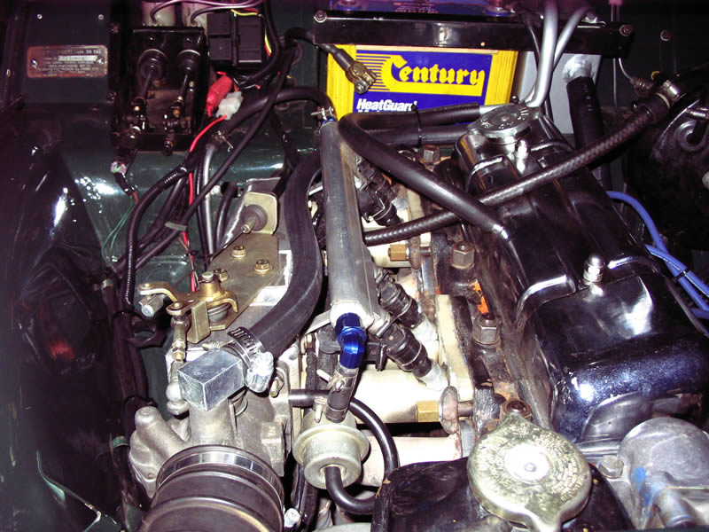 |
Drivers side view of final set up. |
ECU Mounted. |
Front view of final set up. |
 |
 |
 |
Fuel Pumps & Surge Tank. |
Fuse & Relay. |
General View. |
 |
 |
 |
Passenger side view of final set up. |
View fron Passengers side. |
View fron Drivers side. |
 |
||
Throttle Cable. |
||
CLICK IMAGE TO VIEW FULL SIZE |
||